


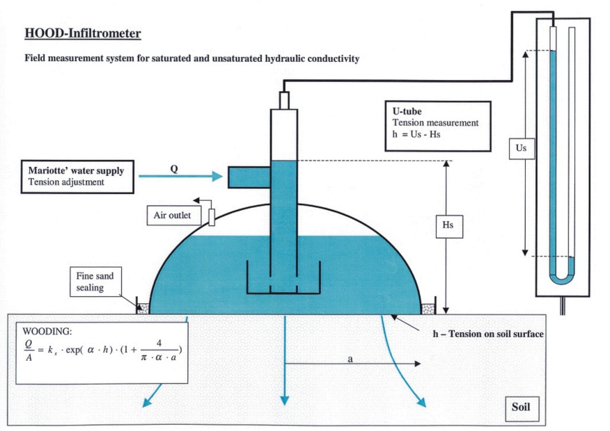
Field measurement and calculation of the unsaturated hydraulic conductivity K(h) using Hood Infiltrometer (Umwelt Geräte Technik, GmbH.): The Hood Infiltrometer IL-2700 is a device used for determination of saturated and unsaturated hydraulic conductivities in-situ. Compared to other Infiltrometer designs (e.g. Perroux and White, 1988; Ankeny et al, 1991; Vandervaere et al., 1997; Špongrová et al., 2009 and others), infiltrating water is in direct contact with the infiltration surface, there is no need for any contact material, and only cutting the vegetation cover to the approx. 5 mm height is needed. The contact material creates an additional layer, which can affect the infiltration process and makes the subsequent data analysis more complicated.
This procedure is demonstrated step by step here on the video. However, reading the following text carefully is recommended before watching the video.
1. Setting of the Infiltrometer |
|
- Select a level measuring site and place all the equipment on the position and try various possible connections and tubing lengths. If needed, cut the vegetation cover to a height of cca 0.5 cm.
- Drive the metal ring into the soil (several milimetres at least, the best if possible is from 1.5 to 2 cm) and place the Hood into its centre. Seal the Hood to avoid unwanted air entry points; fill the gap between the Hood and the metal ring with fine sand and moisten the sand.
- Connect the Hood to the infiltration reservoir and the Hood to the U-tube water manometer.


- Shut all the valves and pull the air intake tube out of the Mariotte bottle (bubble tower). Fill the Mariotte bottle to the mark and re-insert the air intake tube. Fill the water reservoir to the mark. Fill the U-tube manometer to the zero mark.
- Fill the inner yellow vessel inside the Hood. Open the main valve connecting the bottom of the water reservoir and the Hood. The water should flow gravitationally into the Hood. If it does not, raise the adjustable legs carrying the water reservoir.
- Fill the Hood up to the mark on the Hood (it is recommended to hold the Hood downwards to the soil surface by hand). Open the connection valve between the U-tube manometer and the Hood.
- Connect the IL-2700 datalogger. It has two possible inputs: i) on the right-hand side for the data cable connecting the datalogger and PC, ii) on the left-hand side for data cable connecting the datalogger and pressure transducer reading the water level heights in the reservoir.


- Set the required tension. Use the blue balloon to raise the water level into the tube placed in the top of the Hood, and read the value of Hs. Read the value of Us, reading of water level difference in the U-tube water manometer. If Hs is equal to Us, the set pressure head is 0 cm. The difference between Hs and Us gives the set pressure head in cm (see on Fig 2). Move the air intake tube down or up to set the required pressure head. To increase the pressure head to more negative values, push the air intake tube down.
 |
  |
- Start the infiltration by opening the main valve. Thereupon, infiltration is taking place.
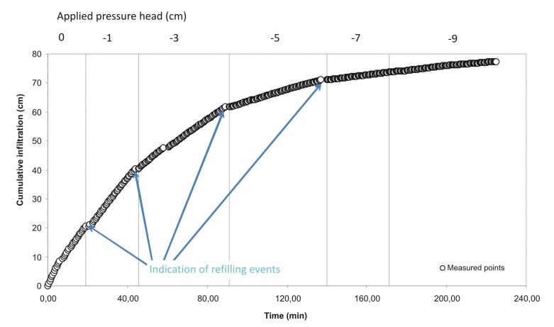
- The datalogger shows actual water level readings together with information about the actual infiltration rate in mm of water level drop per selected sampling time interval.


- It is necessary to let the water infiltrate for long enough to reach the steady-state infiltration rate to enable the steady-state data analysis suggested by Wooding (1968) and Reynolds and Elrick (1991).
- After the steady-state infiltration rate is reached, another pressure head (with a more negative value) can be set and the water can infiltrate further. Again, it is vital to wait until the steady-state infiltration rate is reached.
- If needed, the water reservoir can be refilled. The recommendation is to refill the water reservoir before changing the pressure head settings. The main valve at the bottom of the reservoir needs to be closed before opening the rubber stopper at the top of the water reservoir. Refill the reservoir as quickly as possible. When the reservoir is full, insert back the rubber stopper and slowly open the main valve.
- Repeat the measurements of steady-state infiltration rates for all required pressure heads between “zero” and “soil bubbling point”.
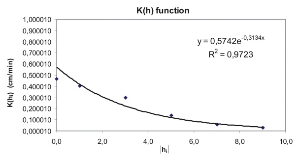
- Different data analyses can be applied on the measured infiltration data. The manufacturer of the Hood Infiltrometer recommends analysis for multiple tension measurement from a single disc method based on the steady-state infiltration data.
- Firstly, the parameter α needs to be determined for neighbouring values of the chosen water pressure heads (h1 and h2) for which applies:
 | Where: |
Q1 is a steady-state infiltration flow rate value (L3 T-1; e.g. cm3 min-1) for previously set pressure head (tension) h1 |


- Check the charge level of the battery in the datalogger, have a spare battery during your field work.
- Make sure you have enough water for the infiltration experiment; or that there is a source of water present close to your field work.
- Avoid any tensile load on the data cable.
- Put a protective mat on the infiltration surface under the Hood to avoid soil dispersion and consequent pore clogging.
- Fill the Hood and the reservoir to the marks, no higher.
- During infiltration, keep an eye on the water level in the Hood; no bubbles should be present and the water level should be kept constant. If not, there are two possible reasons:
i) the soil bubbling point was reached and the infiltration needs to be stopped or carried out with a less negative pressure head
ii) there is an air leaking from some part of the system; all tube connections and valve settings needs to be checked.
Source data: Transfer the raw data as they were recorded by the datalogger (Micrologger IL-2700) into the computer. Follow the instructions mentioned in the User’s manual and import the recorded .DAT file.
Open MS Excel, use command “Open” and find the downloaded .DAT file. Follow the dialog and open the file, store it as an .XLS file.
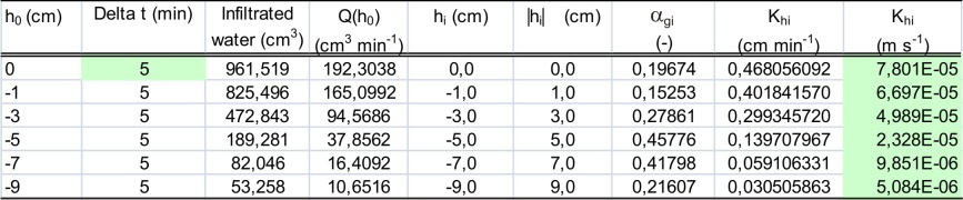
Beginning of the data analysis for the first applied pressure head (0 cm) with all required data is displayed in the table on the right (Tab 1). Data recorded during last 5 minutes of each infiltration phase (each applied pressure head) were assumed to be steady-state infiltration data and were used in calculations. |
|
It is important to carry out the experiments and the data analysis as properly as possible. There is no reference method, which can be used for the resulting K(h) data comparison and check.
Ankeny, M.D., Ahmed, M., Kaspar, T.C., Horton, R. (1991) Simple field method for determining unsaturated hydraulic conductivity. Soil Science Society of America Journal, 55, 467 – 470.
Nielsen, D.R., Wendroth, O. (2003) Spatial and Temporal Statistics: Sampling Field Soils and their Vegetation. GeoEcology textbook, Catena Verlag, Reiskirchen, Germany, 398 pp. ISBN 3-923381-46-8
Perroux, K.M., White, I. (1988) Designs for disc permeameters. Soil Science Society of America Journal, 52, 1205 – 1215.
Reynolds, W.D., Elrick, D.E. (1991) Determination of hydraulic conductivity using a tension infiltrometer. Soil Science Society of America Journal, 55, 633-639
Vandervaere J.P., Peugeot, C., Vauclin, M., Angulo-Jaramilo, R., Lebel, T. (1997) Estimating hydraulic conductivity of crusted soils using disc Infiltrometers and minitensiometers. Journal of Hydrology, 188/189, 209 – 223.
Wooding, R.A. (1968) Steady infiltration from a shallow circular pond. Water Resources Research, 4, 1259 – 1273.
Špongrová, K., Kechavarzi, C., Dresser, M., Matula, S., Godwin, R.J. (2009): Development of an automated tension Infiltrometer for field use, Vadose Zone Journal, 8, 810 – 817.
Note: Fig 1 and Fig 2 are taken from the guide "Operating instructions for Hood Infiltrometer IL-2700" provided with the equipment, and adapted.

