


Measurement of saturated hydraulic conductivity at a locality with available groundwater level in measured layer is best operated by using the auger hole method. This method is quick and easy and does not demand any expensive equipment. Moreover, natural water from the place being measured is used for the experiment.
Watch the video to see how this method is carried out.
Soil auger with suitable diameter, extension rods with connecting pieces, bailer or pump, folding rule, float gauge set consisting of measuring tape, measuring tape holder and float, stopwatch, equipment for writing records, plastic foil, optionally an equipment for soil sampling.
1) Drilling of the hole
2) Removal of the water from the hole
3) Measurement of the rate of the rise
4) Computation of the hydraulic conductivity from the measurement data
- The hole is bored into the soil to a certain depth below the groundwater (GW) level
- The depth where the GW level is reached for the first time is registered
- Observe the changes in soil characteristics (color, water saturation, etc.)
- Wait until the equilibrium with the surrounding GW is reached (until the GW level keeps constant), the stable GW level is measured


- Ground water is removed manually by using a bailer or pumped out from the hole
- Final GW level after removal is registered


- Use of float gauge with a measuring tape or electrical device
- The observations are most often made at regular time intervals
- About 10 readings is recommended


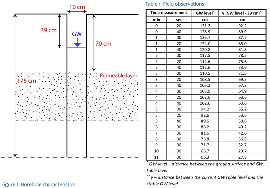
Borehole characteristics, field observations (see Figure 1, Table 1):
Borehole depth 175 cm, radius of the borehole 5 cm, first registration of the GW at 70 cm below the ground surface, stable GW level measured 39 cm below ground surface, water bearing layer in the interval between 70-130 cm below the ground surface, below 130 cm the impermeable clayey sediments begin.
- Borehole radius “r” is in the range 3 cm < r < 7 cmm
- The depth of the water column during the steady state is in the range 20 cm < H < 200 cm
- The depth interval for the recovery observation is y > 0.2H
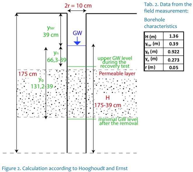
H – stable GW level [m]
yter – depth to stable GW level from the surface [m]
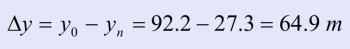
y0 – GW level difference from stable GW after its removal, at the beginning of the rise rate measurement [m]
yn – GW level difference from stable GW at the end of the rise rate measurement [m]
y – GW level during the rise rate measurement [m]
r – borehole radius [m]
The saturated hydraulic conductivity is calculated according to Hooghoudt (1936): 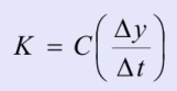
where the value C is a function of y, H, r and the distance between the borehole bottom and the underlying impermeable layer. It is calculated according to Ernst (1950).
Note: the values used in the following equations have to be inserted in cm and s. The result K will be in m/day.
1) (i) 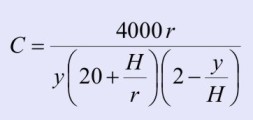 if the impermeable layer is deeper than H/2 below the hole bottom.
(ii) 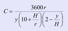 if the impermeable layer is below the hole bottom or at the same level.
Where 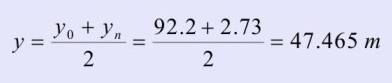
Considering the impermeable layer below 130 cm, our example fits the second equation (ii) better:
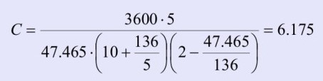
2) 
3) 
The validity of Kirkham's equation is not limited in the value of the depth H as it is in the previous method A). The nomenclature of symbols is the same as for the method A). The figures are recorded in cm and s. The result K will be in m/day.
where: C = 0,617 r / (S H) |
 |
- Simplest method for interpreting piezometer tests and the soil saturated hydraulic conductivity (K) assessment
- Used in shallow saturated groundwater systems which are homogenous and isotropic
H – stable GW level [m]
H0 – GW level after its removal [m]
L – thickness of the water-bearing (permeable) layer [m]
R - borehole radius [m]
r – radius of the casing (r~R if the casing is missing) [m]
y – GW level during the rise rate measurement [m]
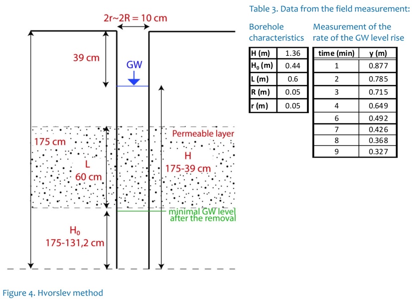
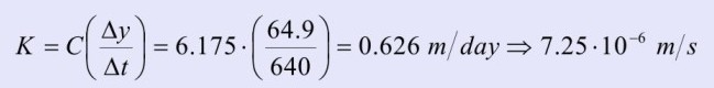
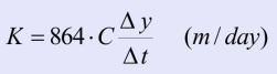
The saturated hydraulic conductivity is calculated according to Hvorslev (1951): 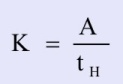
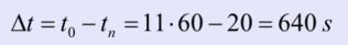
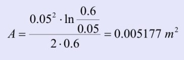
where 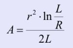 and tH is the value of time at which the experimental curve corresponds to value y = 0.37 m given by the Hvorslev definition.
1) 
2) tH value is possible to acquire using graphical solution, see Figure 5:
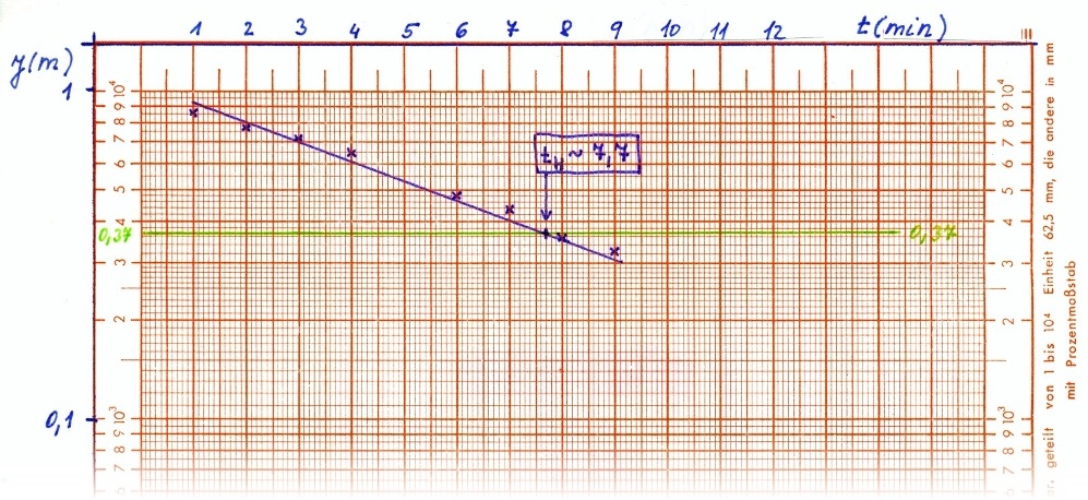
Figure 5. Relation between time and recovery at semilogarhitmic paper.
In our case, the tH = 7,7 min
3) 
- Be careful about the GW level readings – while the measurements are carried out from the ground surface, for the calculation you must convert this number into a distance between the GW level and the bottom of the borehole.
- Pay attention to units – in field often measured in cm while the calculation needs m.
Císler, J. (1967) Metody stanovení koeficientu propustnosti v polních podmínkách. Symposium o půdní vodě, Praha
Chiasson, P. (2005) Methods of interpretation of borehole falling-head tests performed in compacted claz liners. Can. Geotech. J. 42, 72-90.
Chirlin, G.R. (1989) A critique of the Hvorslev method for slug test analysis: the fully penetrating well. Ground Water Monitoring Review. Spring 1989. 130-138.
Ernst, L.F. (1950) A new formula for the calculation of the permeability factor with the auger hole method. T.N.O. Groningen 1950. Translated from the Dutch by H. Bouwer, Cornell Univ. Ithaca, N.Y., 1955.
Hooghoudt, S.B. (1936) Bepailing van den doorlaatfactor van den grond met behulp van pompproeven, (z.g. boorgatenmethode). Verslag Landbouwk. Onder zoek 42, pp. 449-541.
Hvorslev, M. (1951) Time lag and soil permeability in groundwater observations, Waterways, Experiment St. Corps of Eng., U.S. Army, No. 26, 1951:50.
Kirkham, D., van Bavel, C.H.M. (1948) Theory of seepage into auger holes, Proc. Soil Sci. Soc. Amer., 13, 75 - 82