This relatively simple pressure infiltrometer is a Mariotte type infiltrometer constructed from non-corrosive materials (Plexiglas, PVC, Teflon). The device uses the mechanical-hydraulic principle without need of an external energy supply. The device is portable and easy to set up and can be operated by one or two workers. The device enables the measurement with acceptable accuracy of the cumulative infiltration of ponded water from the infiltration ring. The metal infiltration ring (inner diameter of 15 cm) is equipped by its own water gauge for reading the constant water level H in the infiltration ring at a certain time after the start of the infiltration experiment. The depth of metal ring penetration into the soil can be up to 10 cm.
The infiltrometer can supply water during the experiment up to the amount corresponding with saturated hydraulic conductivity
K=77 m day-1.
Watch the video in order to see how to use this pressure infiltrometer.
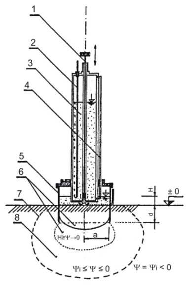 |
Description of the infiltrometer
1 - Piston valve to open or close the water outlet |
The selected spot for the infiltration experiment needs to be prepared first; the grass needs to be cut (or removed). It is also possible to apply this device on the stages of the soil pits. The infiltration ring is then driven (hammered, but with minimum disturbance to the soil) into the soil to the position of the water gauge. A protective pad from the porous material is placed into the infiltration ring to protect the soil surface against clogging. The infiltrometer is then placed on the infiltration ring; the water reservoir is filled with water from a portable water reservoir. Before taking the device into the field, the level of ponded water in the ring was pre-set on the infiltrometer in the laboratory (i.e. 10 cm).
 in operation")


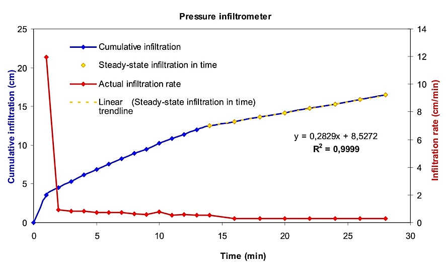
When the valve at the top infiltrometer is opened, the infiltration experiment starts. After several seconds the soil surface inside the infiltration ring is ponded with water, the water level in the infiltration ring rises until it reaches its constant value. The water level in the infiltration ring can be monitored in the water gauge. |
|


The steady-state infiltration, which takes place after longer time period of water infiltration, is generally described by an equation from Reynolds and Elrick (1991) and Reynolds et al. (1985) which has the following form:
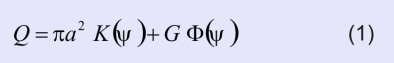 | where Q is the amount of infiltrated water (L3 T-1), a is the radius of the infiltration ring (L), G is the function of the infiltration surface geometry (L), Φ is the flow potential (L2 T-1), ψ is the water potential (expressed as pressure head h in length units (L). |
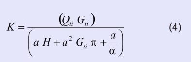
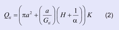 | where Qti is the steady infiltration (L3 T-1), a is the radius of the infiltration ring (L), Gti is the shape factor (L3 T-1), H is the hydraulic head of ponded water in the infiltration ring (L), α is a parameter (L-1) (Philip, 1985 and 1987; for pressure infiltrometers details can be found in Elrick and Reynolds, 1989), K is the saturated hydraulic conductivity (L T-1). |
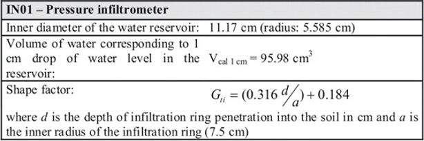
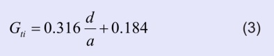 | where d is the penetration depth of the infiltration ring into the soil (L) and a is the radius of the infiltration ring (L) |
 | where h is the water level drop in the infiltrometer reservoir after the elapsed time interval Δt |

Elrick, D.E., and Reynolds, W.D. (1989) Water Flux Components and their measurements. Proc. App. Soil Physics in Stress Environments. Jan 22-26 NARC. Islamabad, Pakistan.
Elrick, D.E., Reynolds, W.D. (1992) Methods for analysing constant head well permeameter data. Soil Science Society of America Journal, 56, 309-312.
Matula, S., Kozáková, H. (1997) A simple pressure infiltrometer for determination of soil hydraulic properties by in situ infiltration measurements. Rostlinná výroba, 43, 405-413.
Reynolds, W.D., Elrick, D.E. (1991) Determination of hydraulic conductivity using a tension infiltrometer. Soil Science Society of America Journal, 55, 633-639.
Reynolds, W.D., Elrick, D.E., Clothier, B.E. (1985) The constant head well permeameter: effect of unsaturated flow. Soil Science, 139, 172-180.
Philip, J.R. (1985) Approximate analysis of the borehole permeameter in unsaturated soils. Water Resources Research, 21, 1025-1033.
Philip, J.R. (1987) The quasilinear analysis, the scattering analog, and other aspects of infiltration and seepage. In: Y.S. Fok (Ed.) Infiltration, development and application. Water resources Research Center, Honolulu, USA, 1-27.