The following text is based on the paper by Matula et al. (2014), which describes the experience of its authors with installation and performance of a small smart field lysimeter SFM-30 (UMS GmbH) on the Experimental Site for Monitoring of Transport Processes and Soil Moisture Dynamics, Department of Water Resources, FAFNR, CULS Prague, located at the university campus. The altitude, longitude and latitude of this site are 281 m a.s.l., 14°22'E a 50°08'N, respectively. The soil is Chernozem on loess; the A-horizon thickness is about 35 cm. The texture is loamy and almost stoneless. The lysimeter is used for observation of water balance and movement in a natural soil profile, while the transport of solutes is currently not in the focus.
Principle
In situ monitoring of soil water regime and balance is very important for understanding and subsequent optimization of crop yields formation in agriculture and of various processes related to forest management, protection of ecosystems and landscape water management. The lysimeter is potentially a highly efficient tool for monitoring of soil water balance. As far as it is known, the first lysimeter was constructed by Philippe de la Hire in Paris in 1688 (de la Hire, 1720; cit. according to Kohnke et al., 1940). Since that time, the lysimeters have been substantially improved. Modern lysimeters are continuously weighed and automatically imitate the water regime of the surrounding natural soil. This makes them capable of investigating the soil water fluxes and the dynamics of other soil water state variables in the soil profile in real time under conditions as similar as possible to the natural ones.
Each lysimeter consists of two basic parts. The first part is the observed soil monolith itself, usually of cylindrical shape and, today, usually continuously weighed. The second part, which may be placed in a separate field box, is the equipment for collecting and measuring the percolated water and also for pumping water back into the lysimeter if this is necessary for maintaining the soil watur status in the lysimeter at the same level as in the surrounding soil. The vegetation cover on the lysimeter surface should be the same as the surrounding vegetation.
Eeach larger lysimeter is designed individually with respect to conditions of a particular location, purpose of research and funds available. Small lysimeters equipped in similar modern way attract attention because of their lower price and larger versatility.
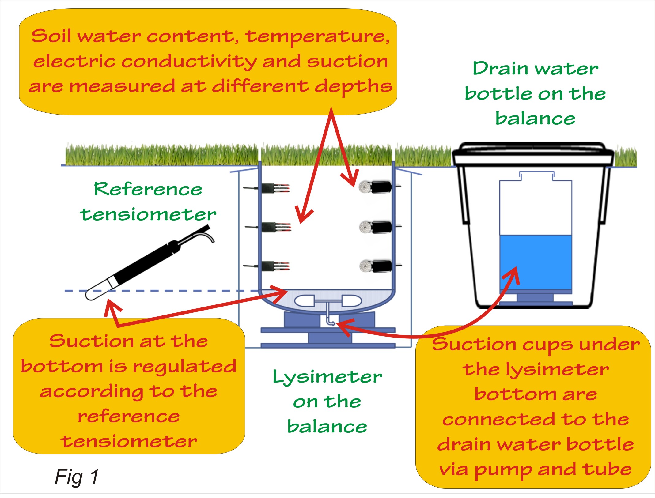
Fig 1 presents a basic scheme of the Smart Field Lysimeter SMF-30 (UMS GmbH, München, Germany; http://www.ums-muc.de). The soil monolith diameter is 30 cm and its height is also 30 cm. It is contained in a stainless-steel cylinder with several access holes on the sides, allowing various sensors to be pushed in. The undisturbed soil monolith must be cut away from the natural soil, using the same the stainless-steel cylinder and a jack, which, in the case of a similarly small lysimeter, can be hand-driven. The cylinder with the soil monolith inside is placed in a protective container (the lysimeter housing), completely hidden under the soil surface, on an electronic balance PL-50 (UMS GmbH.) that weighs it continuously.
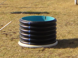
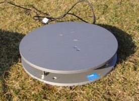
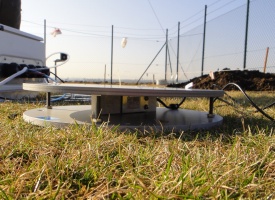
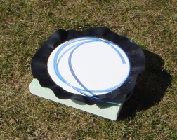
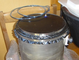
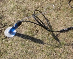
The negative pressure head of soil water at the bottom of the lysimeter is maintained on the same level as that in the surrounding soil. For that purpose, several ceramic suction cups are immersed in the porous material contained in the stainless steel bowl at the bottom of the lysimeter. The correct underpressure of air in the cups is maintained by an electronic bi-directional pump. The underpressure so achieved is measured and recorded. In an older version of the lysimeter (on the photos), this functionis ensured by a flat ceramic membrane. The required underpressure is given by the reading of a reference tensiometer T8 (UMS GmbH.), which is installed in the natural soil at the depth of 30 cm at the distance about 1 m from the lysimeter. In this way, the soil water regime in the lysimeter is made the same as that in the surrounding soil, except for situations when the natural soil becomes too dry and the air entry value of the reference tensiometer and/or the porous material at the bottom of the lysimeter is exceeded, or when the function of the vacuum system is hindered by frost.
The surplus water from the bottom of the lysimeter is pumped to the drain water bottle in the field box (see Fig 1) which is placed on another balance, PL-10 (UMS GmbH) . In the older version, the drain water bottle must be emptied manually and the volume of water must be measured. In the newer version, a bi-directional pump is placed in the field box (in the older version, the pump was placed in the logger box). If the soil at the bottom of the lysimeter is drier than it should be according to the reference tensiometer, water from the drain water bottle is pumped back to the lysimeter via the porous material at its bottom. All measurements are recorder by a datalogger. In the newer version it is dataTaker DT80M (Thermo Fisher Scientific Australia Pty Ltd).
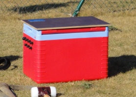
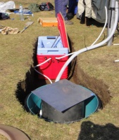
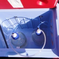
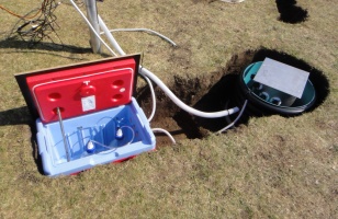
The sensors are inserted into the soil monolith from the sides at three different depths. The set comprises the matrix potential sensors MPS-2 and the soil moisture, temperature and electrical conductivity sensors ECH2O 5TE (both types by Decagon Devices, Inc.). This allows us to study the changes of the variables listed along the vertical direction and in real time. All electrical equipment of the lysimeter is fed by a solar panel with a rechargeable lead battery and/or from the electricity mains. A laminate collar covers the gap between the lysimeter housing and the lysimeter cylinder. It is connected with the cylinder by an elastic sleeve gasket. The collar is placed at a shallow depth under the soil surface and covered with turf.
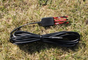
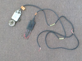
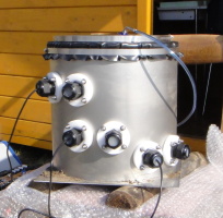
Experience gathered during the lysimeter installation in the field
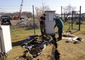
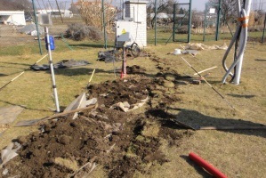
If the work is well organised, the lysimeter can be installed within a single day by two or three workers, of which at least one should be a specialist of the supplier (the exclusive dealer for ČR is Ekotechnika s.r.o.). The first step is the correct choice of a representative site, not shaded against wind, with the soil profile and vegetation typical for the location, allowing easy installation of the two containers, the tensiometer, the solar panel and the logger box with electronics and cables. Then the soil monolith may be cut, using the stainless steel cylinder. The cylinder is pushed into the soil directly on the spot of future lysimeter installation, using a hand-driven jack connected by ratchet tie-downs with steel anchors screwed in the surrounding soil. The friction between the steel cylinder and the soil is reduced by gentle moistening of the cylinder walls. The soil at the outer side of the cylinder is frequently removed. This creates a wider pit into which the lysimeter housing can be later inserted.
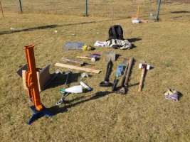
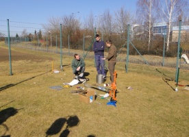
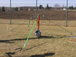
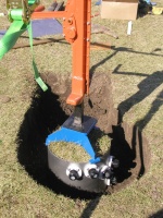
When the cylinder has been pushed to the required depth, the lower base of the monolith is cut off from the natural soil with a thin steel plate or, if conditions allow, simply broken off. The top of the cylinder is then cover with a lid and the cylinder is lifted up from the pit and laid upside down. The pit is enlarged to accommodate the lysimeter housing. The housing is inserted into the pits and the electronic balance is placed onto its bottom. One must keep an eye on the proper depth, in order that the soil surface in the lysimeter is finally set at the same level as that of the surrounding soil.
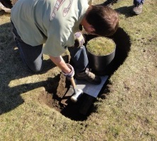
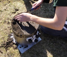
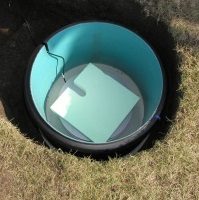
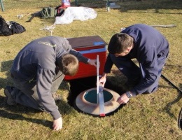
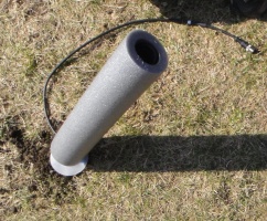
The bottom of the monolith, which is now upside down, is cleaned and made even, but not smooth (in order that soil macropores are not clogged). The bottom bowl with water-saturated porous fill and the suction cups inside (in the older version, the water-saturated porous membrane, as shown on the photo) is attached to the monolith bottom. During the operation, the porous fill of the bowl must be protected by a steel plate against spilling out. When this steel plate has been pulled away, the bowl is fastened tightly to the lysimeter cylinder, making sure that a good hydraulic contact is established between the two. Then the lysimeter may be put upright and then the sensors may be inserted into the holes in the cylinder walls. First, adequate pockets must be gouged out in the lysimeter soil to accommodate the sensor bodies. At the same time, care must be taken to put the sensors into intimate contact with the soil. The matrix potential sensors MPS-2 must be wetted and wrapped with soil slurry before their installation. The prongs of the soil water content sensors must be pushed into undisturbed soil. The flat sensors should be tilted at 45o around their longitudinal axis, so that the percolating soil water does not accumulate on the top of them. Thereby also the thickness of the measured soil layer is reduced. When a sensor has been pushed firmly into the soil, its access hole is closed by a leadthrough plug. In the new version of the lysimeter, the signals of all sensors, including those of the electronic balance and the sensor of pressure head at the lysimeter bottom, are read via SDI-12 (Serial Data Interface at 1200 Baud) protocol, so that only one cable (in addition to a single vacuum house and an earthing cable) is needed to connect the lysimeter housing with the control unit. The connecting elements are lead underground through a protective pipe to the water collecting bottle, the vacuum pump, and the logger box on a short mast.
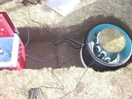
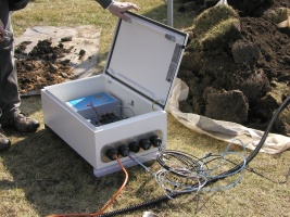
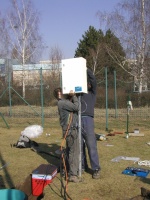
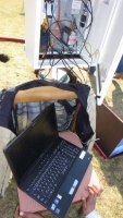
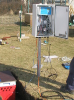
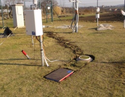
The lysimeter with the sensors, the bottom suction bowl, cables and the wiring box on the side (in the older version: the lysimeter with sensors, cables, and the ceramic membrane with a neoprene envelope) is cautiously laid down on the electronic balance in the lysimeter housing. The container is then overlain by thecollar and soil, so that only the upper base of the lysimeter, overgrown by vegetation (in our case, grass) is visible from above the ground. After some time, the presence of a lysimeter is only betrayed by the light-coloured sleeve gasket connecting the collar with the lysimeter cylinder. The vegetation above the collar usually suffers from drought. It is recommended to irrigate it cautiously, e.g. using a drip irrigation set.
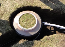
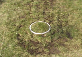
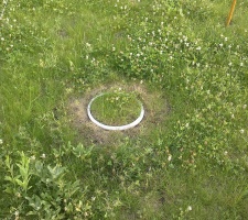
The new version of the lysimeter includes a second container (the field box)which accommodates a drain water storage vessel on an electronic balance and the vacuum pump. At installation, the storage vessel is half-filled with clean local water. The vessel is connected with the outlet of the vacuum pump and a small bottle on the side, which is weighed together with the large vessel and serves the purpose of sampling a smaller amount of percolated water. There is no underpressure in the storage vessel. In the older version (on the photo), the field box contains two non-weighed glass bottles connected in series, in which there is underpressure. The vacuum pump of the older version is placed in the logger box on the mast.
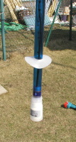
The reference tensiometer (T8 or T4) with a provision for manual deaeration is installed in the undisturbed natural soil with its porous cup at the depth 30 cm at the distance about 1 m from the lysimeter. In the new version, the whole tensiometer withits pressure transducer is buried underground. A layer of soil protects it against the influence of temperature variation. The deaeration tubesof the new version are led from the tensiometer into the storage vessel (field box), while the cable from the tensiometer is led to the logger box on the mast (in both versions).
Experience gathered during performance
Our most relevant experience with the new lysimeter version was gathered in dry summer of 2013, when the soil water pressure around the lysimeter and in the lysimeter itself fell repeatedly below -100 kPa. The reference tensiometer found itself out of measurable range and the porous fill of the bottom bowl and the ceramics of the suction cups became permeable for air; hence the vacuum pump could not hold any underpressure. This, however, was not an essential malfunction from the viewpoint of soil water balance, because the upward movement of water in the natural soil at the depth of the lysimeter bottom in the period of drought is very slow anyway. The question is, whether or not it is possible to realistically measure the downward water movement through the lysimeter bottom, if ample rain comes after a long dry spell, and whether or not a lysimeter can automatically recover after the end of a dry period.
Several dry periods took place during the dry summer of 2013, out of which two are depicted in Figs. 2, 3 and 4. The reference tensiometer indicated for some time low pressures down to -90 kPa, but a comparison with the capacitance matrix potential sensor clearly indicates that these tensiometric readings were false; the soil water potential expressed in pressure units was much lower, approaching in one case -900 kPa, even though the measuring range of the sensor, declared by the manufacturer, should end at -500 kPa (Decagon Devices, 2014). The first period of drought was interrupted in August by rains, which moistened the soil and increased the water pressure at 30 cm so that it was over about a week measurable by the tensiometer. The reference tensiometer was then deaerated and started, for some time, to indicate again pressures about -90 kPa. The drought, however, continued. It was not until October that the soil became moist enough that a repeated deaeration of the reference tensiometer made sense. At that time also the porous fill of the bottom bowl and the suction cups in it became saturated with water, so that the regulation of water pressure at the lysimeter bottom could automatically start again, not requiring any human action, except for the deaeration of the reference tensiometer.
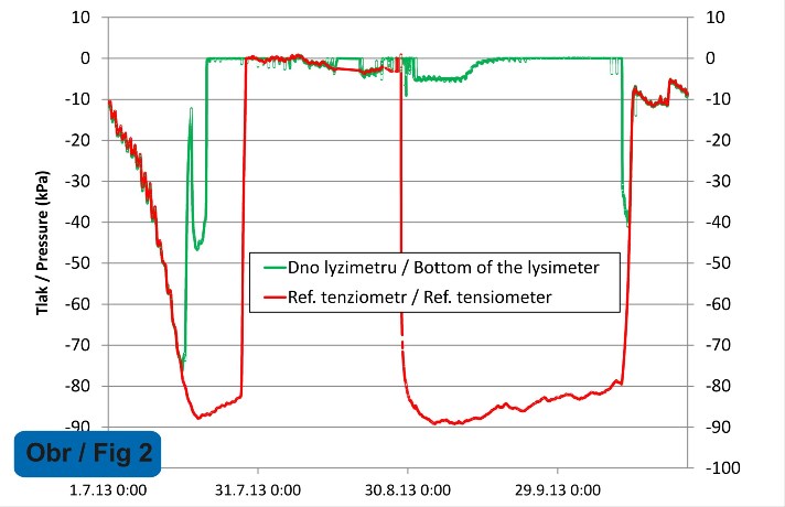 |
Fig. 2 Soil water pressure head variation according to the reading of the reference tensiometer T8 at 30 cm in natural soil, compared with the variation of pressure in the vacuum system connected with the lysimeter bottom; period of drought between 1st July and 24th October 2013. |
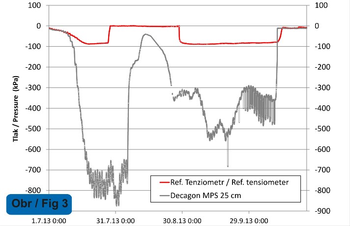 |
Fig. 3 Soil water pressure head variation according to the reading of the reference tensiometer T8 at 30 cm in natural soil, compared with readings of the capacitance porous matrix sensor Decagon MPS-2 at 25 cm in the lysimeter; period of drought between 1st July and 24th October 2013. |
Fig. 4 illustrates a rapid decrease of the lysimeter mass as aconsequence of evapotranspiration over the period of drought and its swift rise due to rains in the middle of the period of interest. The storage vessel mass moderately increased at the very beginning of the period and at its very end, while it remained virtually constant during the drought. Occasional interruptions of the lines in the graph were caused by minor electrical problems that were solved on the spot and did not relate to the essential function of the lysimeter. The storage vessel could not supply water to the backward capillary rise from the lysimeter bottom, because the hydraulic connection between water in the lysimeter and that in the porous material under the lysimeter bottom was interrupted at that time. Some capillary rise was detected in other periods of the year but was always very small, of the order of fractions of a millimetre per day. The downward movement of water and the associated outflow of water from the lysimeter bottom was re-established by the end of the period depicted and there is no reason to assume that this ouflow could be biased towards one or the other side because of the previous drought.
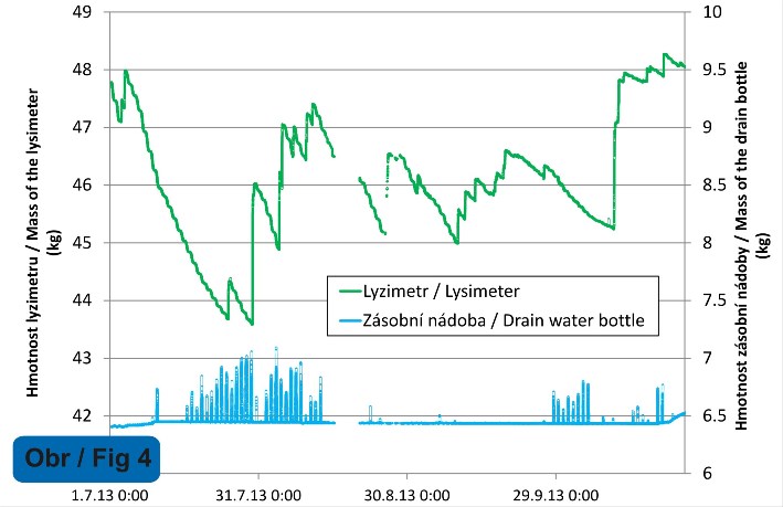 |
Fig. 4 Variation of the lysimeter and storage vessel masses in the period of drought between 1st July and 24th October 2013. |
What we did not expect was the reaction of the vacuum system of the lysimeter to the oncoming drought. It happened that the storage vessel mass quickly rose for one or several hours and then quickly returned back to the original value, while the mass of the lysimeter itself did not change at all (Fig. 4). The phenomenon occurred at approximately diurnal intervals, usually in the middle of the day. We assume that it was caused by the temporary pumping of water into the storage vessel from the connecting hoses and other associated spaces between the lysimeter and the storage vessel. Water in these spaces is not weighed by either of the two balances and they normally do not contain much water or, better to say, the amount of water in them is approximately constant and their disturbing effect is therefore negligible. During the drought, however, the pressure of soil water in the lysimeter decreases sharply during the daytime because of increased evapotranspiration. The air entry value of the porous materials in the bottom bowl is then exceeded for some time. The air from the lysimeter breaks into the vacuum system under its bottom. The vacuum pump tries to draw this air off together with any water present in the system. The water pumped off is put away into the storage vessel. When the critical mid-day period is over, the hydraulic connection with the lysimeter re-establishes and the water is sucked backed into the lysimeter. Analogous peaks are also observable in the graph of pressure beneath the lysimeter bottom (Fig. 2). We regard both types of peaks as artefacts and ignore them during the data processing.
Another extraordinary situation is the winter period of frost. The lysimeter is not designed to resist to severe frosts. If they are about to occur, water must be removed from the vacuum system and the storage vessel. The winter 2013/2014 was, however, very mild; there were only few frost days. We therefore tried to maintain full functionality of the lysimeter even in winter. The result is seen in Figs. 5 and 6.
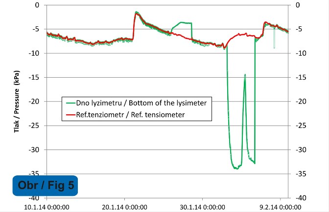 |
Fig. 5 Soil water pressure head variation according to the reading of the reference tensiometer T8 at 30 cm in natural soil, compared with the variation of pressure in the vacuum system connected with the lysimeter bottom; winter period with frost days between 10th January and 9th February 2014. |
The vacuum pump and the hoses connected to it are placed immediately beneath the lid of the field (storage vessel) box; for water in them it is therefore easy to freeze up. Thereby the measurements are disrupted. The short-term freezing up of these parts (or only some spots in them) was observed three times during the winter 2013/2014; in one case it was necessary to disconnect the hoses and remove ice from them. The freezing up is indicated by an increased difference between the soil water pressure according to the reference tensiometer and the pressure measured in the vacuum system. The difference can be positive or negative, as Fig. 5 shows. For reason not yet known to us, the readings of the lysimeter mass also oscillated in these situations (Fig. 6), while the readings of the storage vessel mass were not affected. To avoid these effects, it seems suitable to equip the storage vessel box with a thermostat and to cover it over winter with an insulation layer.
 |
Fig. 6 Variation of the lysimeter and storage vessel masses in the winter period with frost days between 10th January and 9th February 2014. |
Among other pieces of experience gathered over a year of performance, we underline:
1) Because of high thermal conductivity of the metallic case of the lysimeter cylinder, the soil temperatures inside the lysimeter are somewhat higher than those in the natural soil. However, the soil water contents and matrix potential values are statistically in good accordance with those in the surrounding soil.
2) In winter, the solar panel is not capable of supplying enough power to the logger box. A connection to the power mains is therefore necessary.
3) Even in the new lysimeter version, the storage vessel is not equipped with an automated water supply or removal system. Over a little less than a year of performace, it was necessary to remove surplus water three times (altogether about 10 litres), but there was no need to add water.
References
Decagon Devices (2014): MPS-2 Dielectric Water Potential. Product Overview. http://www.decagon.com/products/soils/water-potential/mps-2-water-potential-temperature/ , accessed 21 November 2013.
de la Hire, P. (1720) Mémoires de mathematique et de physique, tirés des registres de l'Academie royale des sciences, de l'année MDCCIII. Remarques sur l'eau de la pluie, sur l'origine des fontaines; avec quelques particularités sur la construction des citernes. Hist. de l'Acad. Roy. des Sci. Ann. 1703 (2): 56-59.
Kohnke, H., Dreirelbis, F. R., Davidson, J. M. (1940) A survey and discussion of lysimeters and a bibliography on their construction and performance. United States Department of Agriculture Miscellaneous Publication No. 372, Washington, D. C., May 1940, 68 pp. http://gis.lrs.uoguelph.ca/agrienvarchives/download/lysimeter_rev_usda_1940.pdf, 20.11.2013.
Matula, M., Miháliková, M., Mráz, A., von Unold, G., Chala, A.T., Hrkalová, M., Doležal, F. (2014): Experience with installation and performance of a small smart field lysimeter SFM UMS. In: Hydrologie malého povodí 2014. ÚH AV ČR, Praha. 22.-24.4.2014.
SmartField-Lysimeter User Manual, UMS GmbH, Munich.
Available at http://ebookbrowsee.net/smartfield-lysimeter-user-manual-v12-2013-pdf-d652390256


